HCF Hydraulic Centrifugal Fan

The DYNASET Hydraulic Centrifugal Fan converts the hydraulic power of a mobile machine, vehicle or vessel into high volume air flow for air blow and vacuum applications.

The HCF Hydraulic Centrifugal Fan is a powerful hydraulic-powered fan designed to generate high-volume airflow for versatile air-blow and vacuum applications. Engineered for reliability and efficiency, this compact unit is ideal for tasks such as industrial vacuum systems, mobile suction units, and more. The HCF is a robust and durable solution, perfectly suited for demanding environments.

Vacuum

Vacuum

HCF 800 40 Hydraulic Centrifugal

Applications

  • Air blowers and fans
  • Industrial level vacuum cleaners
  • Vacuum cleaners
  • Suction units
  • Negative pressure containers

Key Benefits & Features

  • Produces powerful airflow for all vacuum and blowing applications in mobile use
  • The selection includes three different models to accommodate various requirements
  • Airflow capacity ranges from 0.8 m³/sec to 3.4 m³/sec, depending on the model
  • Maximum air vacuum ranges from -11 to -8 kPa, depending on the model
  • Combines air-blow and vacuum functionality into a single unit
  • Compact and robust structure ensures reliable operation in tough conditions
  • Self-cooling design eliminates the need for external cooling systems

Product images

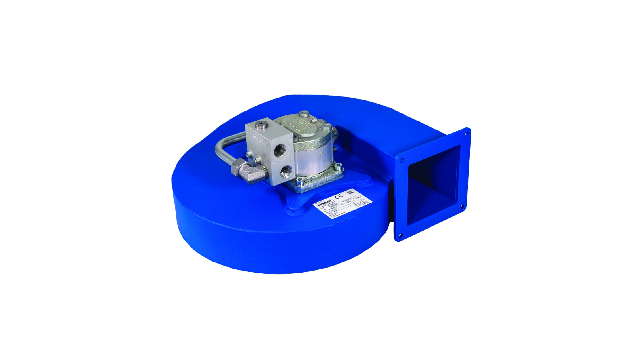
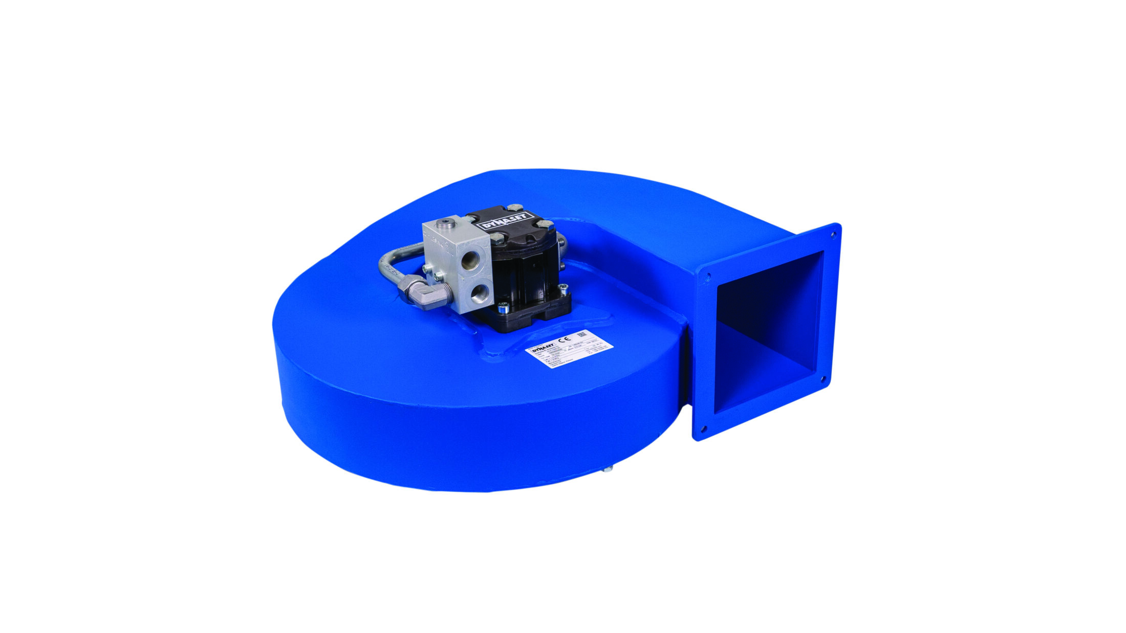
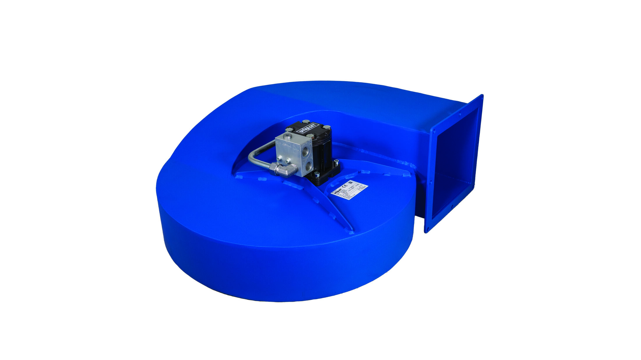
How Does the Hydraulic Centrifugal Fan Work?

The Hydraulic Centrifugal Fan uses a machine’s, vehicle’s, or vessel’s hydraulic system as its power source.

  1. Hydraulic oil flows to the Hydraulic Centrifugal Fan’s integrated hydraulic motor through the pressure line.
  2. The Hydraulic Centrifugal Fan converts the hydraulic oil flow and pressure into high-volume airflow using a high-quality fan blade.
  3. Hydraulic oil is returned to the carrier machine’s hydraulic oil tank via the return line.

Technical details

HCF DATA
HCF-800-40
HCF-1500-50
HCF-3400-90
OUTPUT CHARACTERISTICS
Max air vacuum
kPA
-11
-9
-8
Max air flow
m^3/s
0,8
1,5
3,4
HYDRAULIC CONNECTION
Pressure line
P
BSPP 1/2”
BSPP 1/2”
BSPP 1/2”
Return line
T
BSPP 1/2”
BSPP 1/2”
BSPP 1/2”
HYDRAULIC POWER REQUIREMENTS
Flow max.
l/min (gpm)
40 (10.6)
50 (13.2)
90 ( 23.8 )
Pressure max.
bar (psi)
150 (2200)
210 (2500)
250 (3600)
HYDRAULIC FLUID REQUIREMENTS
Viscosity
cSt
10-200 / optimum 25-35
Temperature
° C (° F)
max. 70 (158)
max. 70 (158)
max. 70 (158)
Filter ratio
μm
25 or better
25 or better
25 or better
OVERALL DIMENSIONS
Lenght
mm (in)
373 (14.69)
478 (18.82)
635 (25.00)
Width
mm (in)
426 (16.77)
544 (21.42)
738 (29.06)
Height
mm (in)
206 (8.11)
238 (9.37)
284 (11.18)

Download

Datasheets

Datasheets

Fill in your information to download the product data sheet(s)

  • This field is hidden when viewing the form
  • This field is for validation purposes and should be left unchanged.

Certificates